Building the ACM Cluster, Part 7: Network redux
Published on in ACM, ACM Cluster
So I’ve mentioned that I’ve been fighting networking again in the ACM cluster. I’ve been reworking the network. This whole adventure began after a conversation with the very knowledgeable nwf, who pointed out that JHU runs two different networks that the ACM systems need access to - CSNet (the JHU Computer Science department’s network) and JHU firewall-free (which has unfiltered access to the internet). The goal of this rework was to allow the cluster to be on both. In a situation with more resources, I would have simply bought another network card for each of the gateway nodes. However, I don’t have those resources and couldn’t find any spare network cards. nwf then pointed out that I would be able to use 802.1Q vlans to make more virtual ports.
So, here’s how this works: CSNet and JHU firewall-free (JHUFF) each plug into a single port on the main switches. These ports are assigned as being on specific vlans that differ from the other ports on the switch. The gateway nodes are trunked, which means that they see the raw traffic - that is, they get packets with the 802.1Q vlan tags intact. (Typically, switches remove these tags before they pass packets through the ports). In my case, I’ve got the gateway nodes bonded into the switch, in order to double their bandwidth. In this context, bonded means that the server can send a message through either interface in order to (roughly) double the bandwidth. The rest of the ports on the switch are then left on the default vlan.
If you think pictures work better, take a look at this one: ACM Cluster Network Diagram.
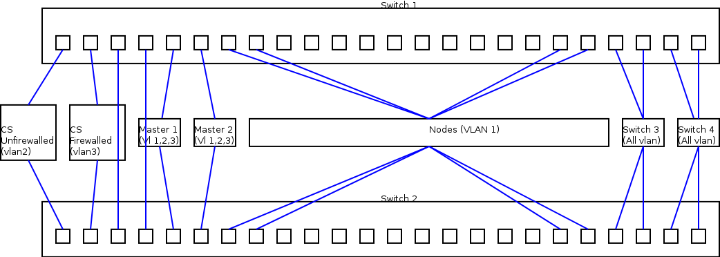
Switch Setup
Fortunately, the switch setup is fairly simple. We simply add the following (in my case) to the configuration file:
interface FastEthernet0/1
 switchport access vlan 2
!
interface FastEthernet0/2
 switchport access vlan 3
!
interface FastEthernet0/3
 switchport trunk encapsulation dot1q
 switchport mode trunk
Note that those last 3 lines are repeated for any port that is being directed to a gateway server. In this case, port 1 is the JHUFF. I’ve marked it as on vlan2. Port 2 is JHUCS, on vlan3. Note that vlan1 is the default vlan, so I’ve left that unassigned to the “special” ports. This way I don’t have to explicitly assign anything to any port which should ‘just work’.
At this point, the switch is not quite all set, but I’ll leave the configuration of that part until later. After I tell you how I messed up my upstream network(s) the first time I was setting this up.
Gateway Server Setup
The gateway node setup comes in two steps. First, bonding the interfaces together, then creating virtual interfaces to get vlan traffic. I highly recommend you do this on a local or otherwise not network-dependent console, because if things are just slightly wrong… you’ll need physical locality to fix them.
Bonding interfaces
Bonding linux interfaces is a fairly common task - It just makes the two interfaces present to userland as one interface and allows the kernel to pick which of the two (or more) physical interfaces to send out of. It is used for a number of purposes - higher bandwidth and redundancy, for example.
Creating bonded interfaces in CentOS is pretty easy. First, lets create the configuration file for bond0 (our bonded interface):
$ sane-editor /etc/sysconfig/network-scripts/ifcfg-bond0
And make the file look like:
DEVICE=bond0
BOOTPROTO=none
ONBOOT=yes
USERCTL=no
Next, we need to slave eth0 and eth1 to bond0. For purposes of brevity, I’m only going to show you eth0’s configuration. I’ve bolded the parts that will need changing in eth1.
DEVICE="**eth0**"
BOOTPROTO="none"
ONBOOT="yes"
MASTER=bond0
SLAVE=yes
USERCTL=no
Again, repeat this for every interface you’d like to be a slave of bond0. Restart networking by running
# service network restart
and check that bond0 came up ok.
In my case, the CentOS boot scripts also would not bring up the interface unless the bonding module was explicitly loaded. In order to do this, run:
# echo modprobe bonding >> /etc/rc.modules
# chmod +x /etc/rc.modules
Note that if you explicitly assign an IP address (or other startup mode, like DHCP) to bond0 (which I have not done, because it shouldn’t have one), you most likely will not need to do this.
Enabling VLAN-Specific interfaces
Okay, now we need to actually have the gateway server separate traffic out by vlan so we can run services on only specific vlans. We do this because some services (DHCP, NFS, DNS) should not be externally exposed. As with the bonded interface, we’ll create these interfaces by editing files. To create an interface that goes directly to vlan1, create /etc/sysconfig/network-scripts/ifcfg-bond0.1 and put the following in it.
DEVICE=bond0.1
BOOTPROTO="none"
ONBOOT="yes"
TYPE="Ethernet"
USERCTL=no
VLAN=yes
Yes, theres some magic here - the system intuits the vlan you’re interested in from the number I’ve bolded above. If you change that (and the name of the file), you’ll create a interface that is tied to that vlan.
Problems (and Solutions)
If you’ve been paying attention here, you’ll see a problem with this setup. In this case, bond0, in non-promiscuous mode, reflects vlan1. But, in promiscuous mode, you can see traffic for all vlans. The problem is that DHCP must be promiscuous so it can see DHCP requests. Unfortunately, this means that it is impossible to listen only on the native vlan for DHCP requests. In my case this is very bad, since the other vlans already have DHCP servers and running mine on these vlans would interfere with these.
In fact, I did this by accident. When I first started this up, I ran it on the bond0 interface. Unfortunately, this started responding to DHCP requests on CSNet. The CS sysadmins very quickly hunted me down and asked me to shut it down, as it was preventing their machines from properly DHCPing.
There are two possible solutions to this problem: change the native vlan that we get from the port and create an interface that specifically can only get the native vlan’s traffic.
Changing the native VLAN
This solution will not work if you have the Cisco switches I have. However, if you have sane switches, give this a shot first - its much simpler. The basic idea is to force your switch to vlan tag the traffic going over the trunk. In my case, this was accomplished by adding the line
switchport trunk native vlan XX
to the interface configuration options for the ports going to the gateway servers. (XX represents an otherwise unused vlan). By doing this, you can run your DHCP server on the interface that is specifically yours. DHCP requests from the other vlans will not reach it, since the operating system strips these out before they reach the server.
Down the Rabbit Hole
However! Here I started running into problems. My switches wouldn’t DHCP anymore. After much frustration, I broke out my best friend in network debugging, wireshark, and took a look. After isolating the right packets, this is what I saw:
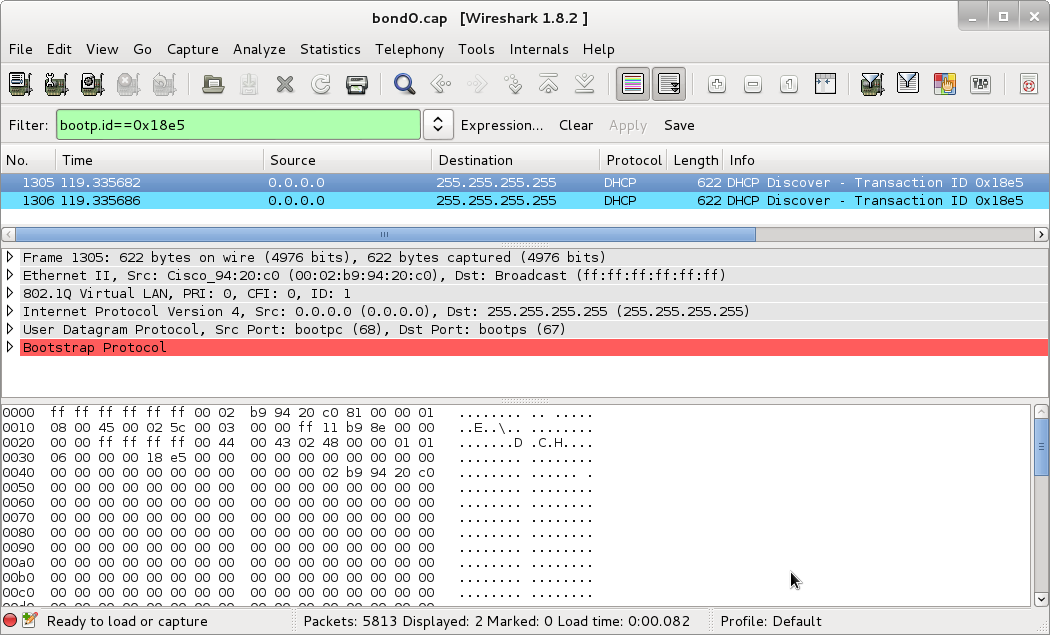
(Click to enbiggen - Download this capture)
See that bright bar of red? That indicates that WireShark believes this packet is malformed. See the lack of responses? That sealed the deal for me - these packets are malformed! And badly!
In order to verify that this was actually a deformed packet, I went back to an older configuration where DHCP was sent without vlan tags by the switch. Turns out that in this case, yes, the DHCP packets are properly formed if they are not vlan-tagged.
Well. Crud. I cannot use non-vlan tagged packets because then I’d be answering on CSNet again. So because of this bug, this method is totally unsuitable for me. However, if your switches do not exhibit this bug, it ought to work quite well and be quite simple to set up.
Creating a pseudo-vlan interface
This method is one I’ve built explicitly to work around the bug I just detailed. In order to do this, we’re going to use ebtables, which does layer2 filtering of packets. This means that it operates at the same level as ethernet and vlan tagging - just what we need!
Set up Bridged Interface
Ebtables is designed to filter traffic crossing a bridge. In this case, since we’re the endpoint, we’re doing something dumb: setting up a bridged interface with only one end point. So lets get started. Create /etc/sysconfig/network-scripts/ifcfg-bond0.def. Bond0.def is my name for the interface that gets only default vlan traffic that enters on bond0. Feel free to change the name to something else you think is more useful or clear. Anyway, make the contents of that file:
DEVICE=bond0.def
TYPE=bridge
BOOTPROTO=none
ONBOOT=yes
NETWORK=172.16.0.0
NETMASK=255.240.0.0
IPADDR=172.16.0.2
You’ll note I’ve also set an IP address here. Since this interface represents the gateway node to the default vlan, it ought to have an IP address.
We also need to change /etc/sysconfig/network-scripts/ifcfg-bond0 to contain the line:
BRIDGE=bond0.def
And restart networking:
# service networking restart
Hopefully everything comes up okay, in which case, move on to the next step.
Here what we just did: By slaving bond0 under bond0.def, we’ve ensured that anything listening or sending on the bond0.def interface can see all traffic on bond0. So whats left is limiting the traffic that bond0.def can see to only non-vlaned traffic.
Set up ebtables
We’ll be using ebtables to limit the traffic to bond0.def. First, lets install ebtables:
# yum install ebtables
Next, set up the ebtables rule that will drop all vlaned traffic:
# ebtables -A OUTPUT -p 802_1Q -o bond0.def -j DROP
Then save the rule:
# service ebtables save
And finally, lets make ebtables start on boot (and start it right now):
# chkconfig --level 2345 ebtables on
# service ebtables start
And that’s it! This ebtables rule looks for any 802.1Q traffic (via -p (for protocol)) destined for bond0.def (the -o, for output, flag) and drops it (-j DROP). I cannot promise this is the most efficient way to do it, but it certainly works.
One More Problem…
So even after all of this, my switches are not DHCPing properly. I’ve done the Wiresharking, and it looks like the switches simply don’t accept the DHCP response. Since this worked before I introduced the vlans, I can only conclude that DHCP on these switches (which yes, are running the latest version of the software) is broken if vlans are enabled. This conclusion is further backed by the fact that the DHCP requests are still malformed.
At this point I need to give up on completely on dynamic configuration. There are simply too many bugs in Cisco’s firmware and I’ve spent too much time working around them. I’m choosing to, in my instance, stay with the bond0.def setup. I feel like this is a cleaner setup than hacking around inside the switch.
So. The solution I’m going with to configure the switches is to write the configuration to NVRAM. You’ll probably want to write at least your basic vlan numbering to the switch’s NVRAM. Otherwise, before the switch DHCPs, it will pass all traffic on all interfaces through untagged. Which could wreck havoc while the switch finds its configuration. Oh, and I cover building this configuration a little further down in this article.
There are a couple of ways to get the configuration onto the NVRAM. The first is to do the configuration on the switch. This is the way configuration like this is typically done. I’m going to pass on this because I’d like to have some central repository of all my configuration. This leaves transfer via tftp and via xmodem.
Xmodem
Xmodem transfer is done via serial cable. I use minicom, since it is easily capable of doing this. Start up minicom on the device connected to the switch (usually /dev/ttyS0). Then run the following on the switch:
> enable
# copy xmodem: flash:config.text
At this point, press control-A, then S. Then select your configuration file and send it. I’ve had cases where I had to restart minicom to get this to work. No I don’t know why.
# reload
The switch reboots and will come up with your new configuration.
TFTP Transfer
TFTP is really convenient for updating configuration over the network. However, it requires that your switch be properly talking to the network. If thats not the case, you’ll have to use xmodem transfer.
> enable
# copy tftp://[tftp server]/[config file] flash:config.text
At this point, the file transfers. Now reboot the switch:
# reload
Final Embedded Configuration
Okay, now lets run through the final configuration that I’ve uploaded to the switches. I’m going to run through it piece by piece. So lets get started with the generic header junk:
!
version 12.0
no service pad
service timestamps debug uptime
service timestamps log uptime
no service password-encryption
Nothing interesting here, so lets move on:
!
hostname eth-switch1
!
enable password [password]
!
The first part of this sets the hostname you’ll see when you log in. The second sets the password you’ll need to input to enable privileged commands on the switch.
Next, interface configuration:
interface FastEthernet0/1
 switchport access vlan 2
!
interface FastEthernet0/2
 switchport access vlan 3
!
interface FastEthernet0/3
 port group 1
 switchport mode trunk
 switchport trunk encapsulation dot1q
 switchport trunk allowed vlan all
!
interface FastEthernet0/4
 port group 1
 switchport mode trunk
 switchport trunk encapsulation dot1q
 switchport trunk allowed vlan all
!
interface FastEthernet0/5
 switchport mode trunk
 switchport trunk encapsulation dot1q
 switchport trunk allowed vlan all
!
interface FastEthernet0/6
 switchport mode trunk
 switchport trunk encapsulation dot1q
 switchport trunk allowed vlan all
!
Okay, lots here, but it should be fairly simple to walk through all of it. As I mentioned at the very beginning FastEthernet 0/1 and 0/2 go to our upstream connections. To segregate them from the rest of the network, I put them on vlan 2 and vlan 3 respectively. switchport access vlan X is the Cisco configuration command to put a port on a specific vlan.
Next, FastEtherenet 0/3 and 0/4. These are the trunked lines from this top switch to the secondary switch. port group 1 tells the switch that these two ports go together and traffic needs to be sent to only one of the two. The next three lines turn this into a trunked interface that receives all vlans.
FastEtherenet 0/5 and 0/6 are the same as 0/3 and 0/4, except that they’re not grouped, since they run to the primary and secondary master/gateway nodes.
The next section deals with SNMP setup. (Remember that? Its how the master node can find out who a new node should be).
ip default-gateway 172.16.0.1
snmp-server engineID local 0000000902000002B99420C0
snmp-server community public view v1default RO
snmp-server chassis-id 0x0E
snmp-server host 172.16.0.1 trap public  entity snmp
!
This instructs the switch that it should send SNMP traps to 172.16.0.1 whenever a new machine connects to it.
Now, some final cleanup stuff:
enable secret 5 [encrypted password]
!
line con 0
 transport input none
 stopbits 1
line vty 0 15
password [password]
 login
!
end
These deal primarily with access passwords. Simply consider them magic. I do - I configured a switch with the right passwords and then ran
Switch# show running-config
to get these lines.
Conclusion
Well, here ends my great networking adventure. This should bring to a close my work with the ethernet network layer in the cluster. At some point I will have to play with the fiber network, but that should be simpler. We’ll get to that at some point…
Anyway, some lessons learned:
- Make sure whatever software you’re using has a way to report bugs and ask for bugfixes
- Simple is good
- Sometimes things don’t work exactly as one would hope
Anyway, after 2+ weeks of spending my spare time fighting this issue, it is time for me to move on and try to get the nodes functioning. So that’s where I’m headed next!