Smarter Cat Feeder Part 1: Intro & Hardware Checkout
Published on
This post is the first part in my series on making a smarter cat feeder. When it’s complete, I’ll add a link to the “how-to” here.
Motivation
I have two cats who I love very dearly. I also occasionally travel for short enough times that it does not make sense to leave the cats with someone. While someone has to stop by to do some tasks (like emptying the litterbox) asking someone to come by to feed them four times a day would be excessive.
So I bought some automated feeders. Specifically the Trixie TX7 (page in German, because I’m not aware of them being sold on english sites). At the time of writing, this feeder is listed at €85. I bought them fo €57. Honestly, for the current price, I’d pay the €5 extra to get something better-designed and already app-controllable. But I bought these years ago, and it was a €100 euro jump to something similar…
Anyway. I have these feeders. Mechanically they work pretty well, but they’re basically timers that occasionally move a motor and play sound. I want a few extra features:
- A camera, so I can look and see the cats. I usually leave a laptop running streaming software pointed at them so I can see the cats eat, but it would be nice to integrate this into the feeder.
- Remote control of the food timing. When I’m home, the cats get two meals of wet food and two of dry. Often, when I’m leaving, I’m able to give them a meal of wet food. But that means they sometimes overeat, if the automatic feeder feeds them shortly afterwards. It would be good if I could remotely and dynamically adjust the feedings.
- The feeders can play audio while dispensing food to help call the cat. It might be nice to take that one step further and allow playing live audio and thus allow some degree of remote interaction with the cats.
- The feeders do have one mechanical flaw: They use an auger to move the food from the hopper to the bowl. The auger does not reverse after serving the food, meaning that there’s some food at the angle of repose, ready to come out if the feeder is disturbed. The cats have figured this out, and my female cat will hit the feeder (or stick her nose up the auger) in order to get extra food at any particular mealtime.
So my feature list is:
- Allow remote viewing via a camera
- Allow remote control
- Allow the auger to be reversed after feeding
- Maintain the ability to play a recording while dispensing food
- (Optionally) live stream audio from a device to the feeders
Which probably makes it about equivalent to this top-of-the-market feeder. The camera appears to be the major value add here, because app-controllable feeders can be bought for a lot less.
Feeder Teardown
Let’s start by getting our hands dirty and taking this feeder apart! That will give us an idea what we’re working with and what parts we actually need.
First, here’s a picture of the feeder fully assembled:

I consider this three major parts:
- The bowl, where food is served
- The core, which contains the auger, electronics and screen
- The hopper, where food for future servings is stored.
Then, just the core module we’ll be modifying:
 .
.
If we flip the core over, there are four screw holes. The screws are long and it takes longer than expected to get them fully apart. But then we get access to the inside:
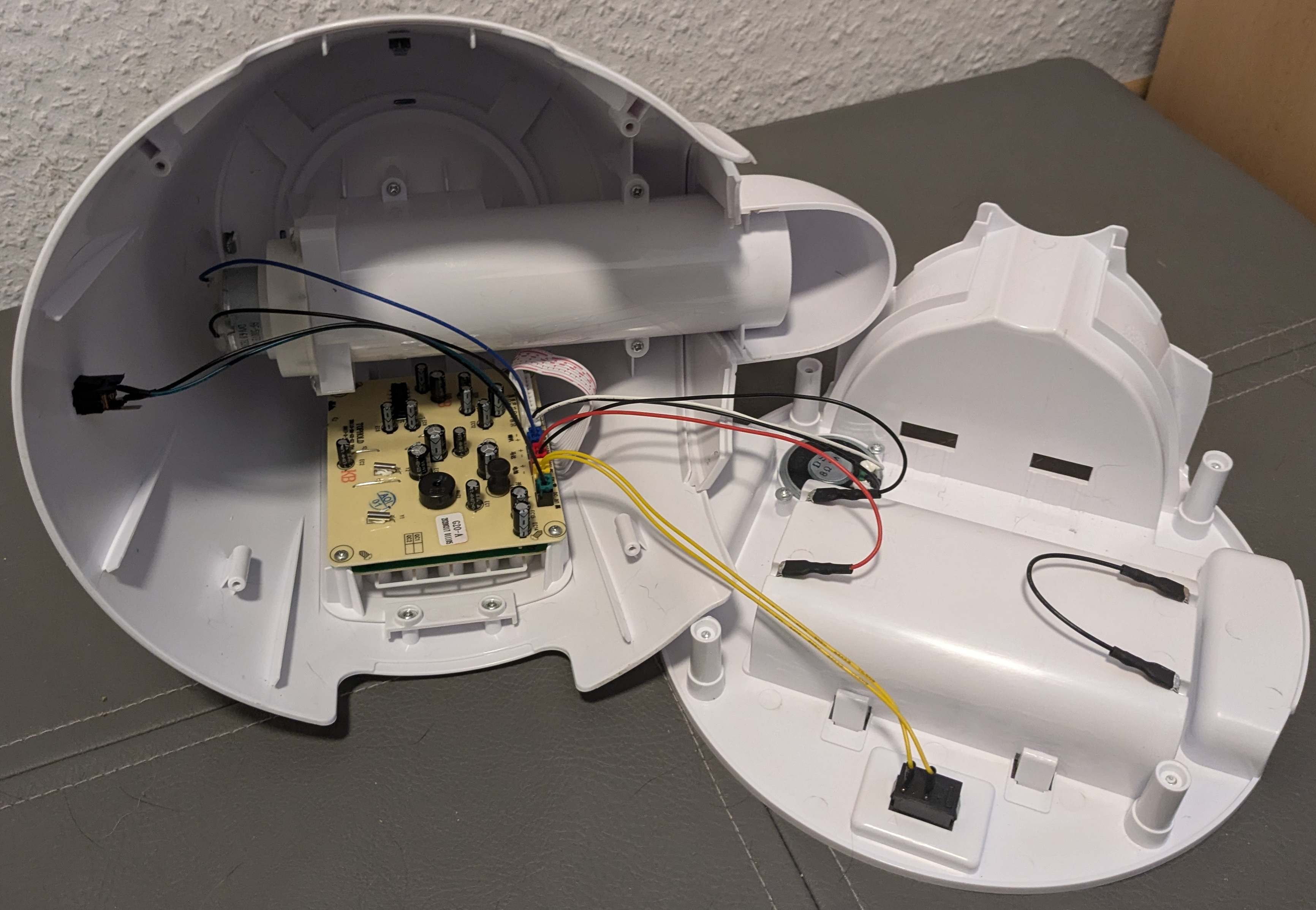
On the base we can see that wires lead to three places. The yellow ones leading to a small back box are power control - the other side of that box (facing the floor in the feeder’s normal orientation) has an on/off switch. The red and black pair leads to the raised white area - the battery compartment, if you ever wanted to power this with D-cells, rather than the USB power cord it comes with. The lonely black wire on the other side of the battery compartment just connects the ends of the batteries. And finally, a black and white pair of wires connects to the speaker, which is facing towards the floor.
The upper part of the feeder contains a lot of interesting parts. Let’s disconnect the bottom for now and take a look at the top:
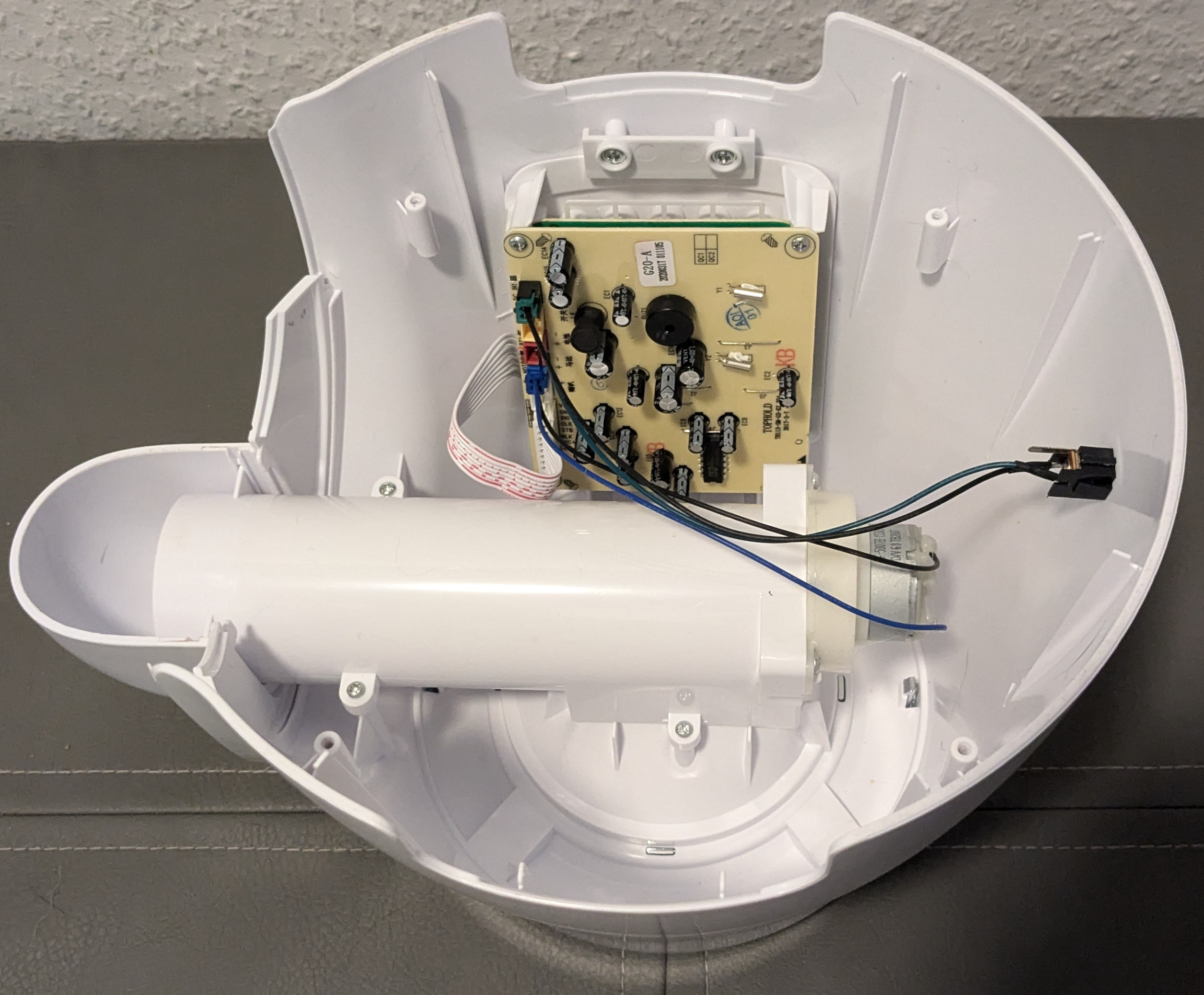
Now we can clearly see the control electronics on the circuit board and that there’s a motor on the back of the cylinder containing the auger. There’s also a place to plug in the power on the right.
Let’s take out the circuit board and look more closely at it. It comes off as an entire electronics module - everything including the screen.
![A closer view of the beige circuit board. Lots of cylindrical black-and-silver capacitors, one integrated circuit, a buzzer, a few ports and some jumpers are all we can see. No traces between components are visible. We can see a ribbon cable that leaves the board and then curves back under it. All the components are labelled in english; the ports are labeled both in english and chinese.]
There’s honestly not much to see here - not even any traces! There’s just one IC. It’s a ISD 1820PY, which is apparently the chip that saves and plays back recorded sound.
The ribbon cable goes off to another board, so let’s remove the screws on this board and open up the module.
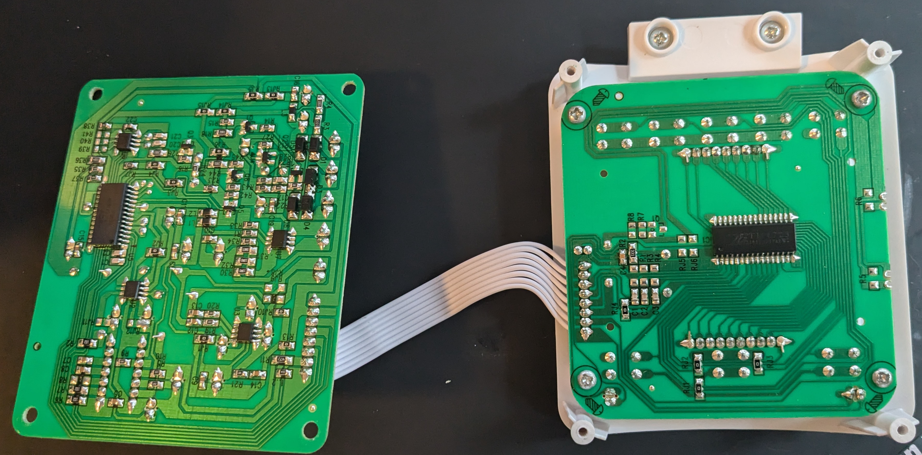
Now we can see traces! It looks like all the tall components got put on one side and small components between the two halves of the module.
The board pictured on the left is the one we just saw the beige side of. The one on the right is connected to the screen.
The ICs are interesting - let’s figure out what they are, starting with the one on the outside board:
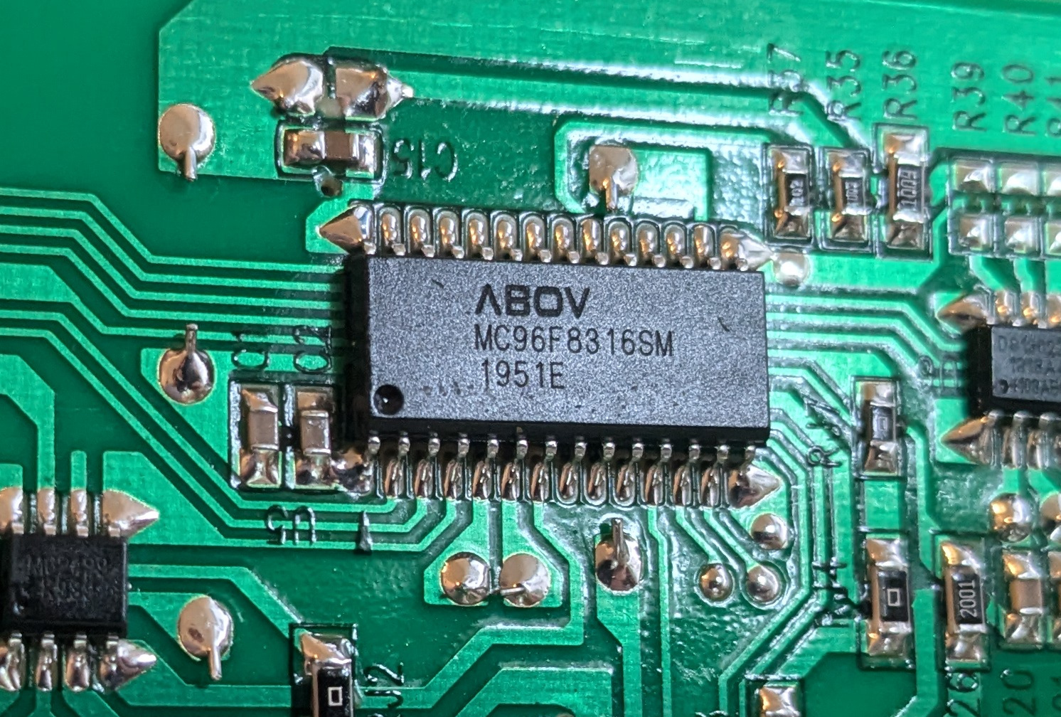
This is an ABOV MC96F8216SM (data sheet). It looks like this is an 8-bit microcontroller based on a Mentor 8051. It has some miniscule RAM, but mostly seems to be geared towards reading inputs, running timers, and running a buzzer. Just about all you’d want for a basic feeder.
Interestingly, the manual talks about doing in-circuit programming. The ribbon cable port has two sets of pinouts marked. The one on the left matches the in-circuit programming lines.
![A close up of a ribbon cable connector on the outer circuit board. We see that it has 8 pins. In the picture, they go from the top of the picture to the bottom. On the left, it is marked, from top to bottom: “VCC”, “GND”, “SDA”, “SCL”. In order, these would be: power in, ground, serial data, and serial clock. On the right, from top to bottom, it is marked “VCC” (power in), “GND” (ground), DIO (unknown), “CLK” (probably clock), “STB” (unknown), “BLK” (possibly for blank), “MIC+” (microphone positive), and “MIC-” (microphone minus)]
If we wanted to we could probably reprogram this. But that would involve a lot of effort reverse engineering the circuit to decide how to write the firmware. And let’s be honest - the device has only 768 bytes of RAM. It can’t even hold a whole picture in memory! Using this for this project would be a waste of time.
However, there’s still another IC on the inner board:
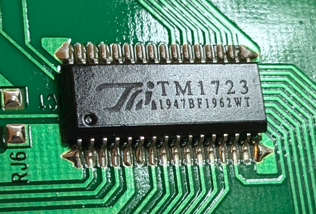
A TM1723(data sheet, not available in english) appears to be nothing more than a display driver that can also sense and pass on information about buttons.
We could take this apart more and take a look at the screen. However, there’s little point when we’ve already discovered we won’t be using it. Perhaps after everything else works, we could consider trying to interface with the display driver.
Conclusion
While it was certainly interesting to tear this feeder down, the real work now begins: building it back up to do more useful things! This is going to be a gut and rebuild job. Next time, we’ll pick out some hardware and lay out at least the initial circuit we plan to use.
Also, if you got all the way to the end, you deserve to be paid your cat tax: